
Fortun365 menggunakan sistem keamanan berlapis dengan enkripsi modern, sehingga data pengguna tetap aman dan aktivitas berjalan tanpa gangguan. Tidak ada manipulasi atau tindakan yang merugikan pengguna.
2.png)
MARKETICA_PREVIEW/00-marketica-preview-sale37.jpg
MARKETICA_PREVIEW/01_marketica2_homepage.png
MARKETICA_PREVIEW/02_marketica2_shop_page.png
MARKETICA_PREVIEW/03_marketica2_single_product_page.png
MARKETICA_PREVIEW/04_marketica2_cart_page.png
MARKETICA_PREVIEW/05_marketica2_checkout_page.png
MARKETICA_PREVIEW/06_marketica2_myaccount_login_page.png
MARKETICA_PREVIEW/07_marketica2_plan_and_pricing_page.png
MARKETICA_PREVIEW/08_marketica2_team_members_page.png
MARKETICA_PREVIEW/09_marketica2_contact_page_template.png
MARKETICA_PREVIEW/10_marketica2_blog_page.png
MARKETICA_PREVIEW/11_marketica2_blog_post_formats.png
MARKETICA_PREVIEW/12_marketica2_single_product_page.png
MARKETICA_PREVIEW/13_marketica2_theme_customizer.png
MARKETICA_PREVIEW/14_marketica2_visualcomposer_templates.png
MARKETICA_PREVIEW/15_marketica2_tablet_view.png
MARKETICA_PREVIEW/16_marketica2_tablet_view_offcanvas_menu.png
MARKETICA_PREVIEW/17_marketica2_themeoptions_header.png
MARKETICA_PREVIEW/18_marketica2_themeoptions_footer.png
MARKETICA_PREVIEW/19_marketica2_themeoptions_contact.png
MARKETICA_PREVIEW/20_marketica2_themeoptions_woocommerce.png
MARKETICA_PREVIEW/21_marketica2_wcvendors_user_page.png
MARKETICA_PREVIEW/22_marketica2_wcvendors_vendor_page.png
MARKETICA_PREVIEW/23_marketica2_wcvendors_vendor_dashboard.png
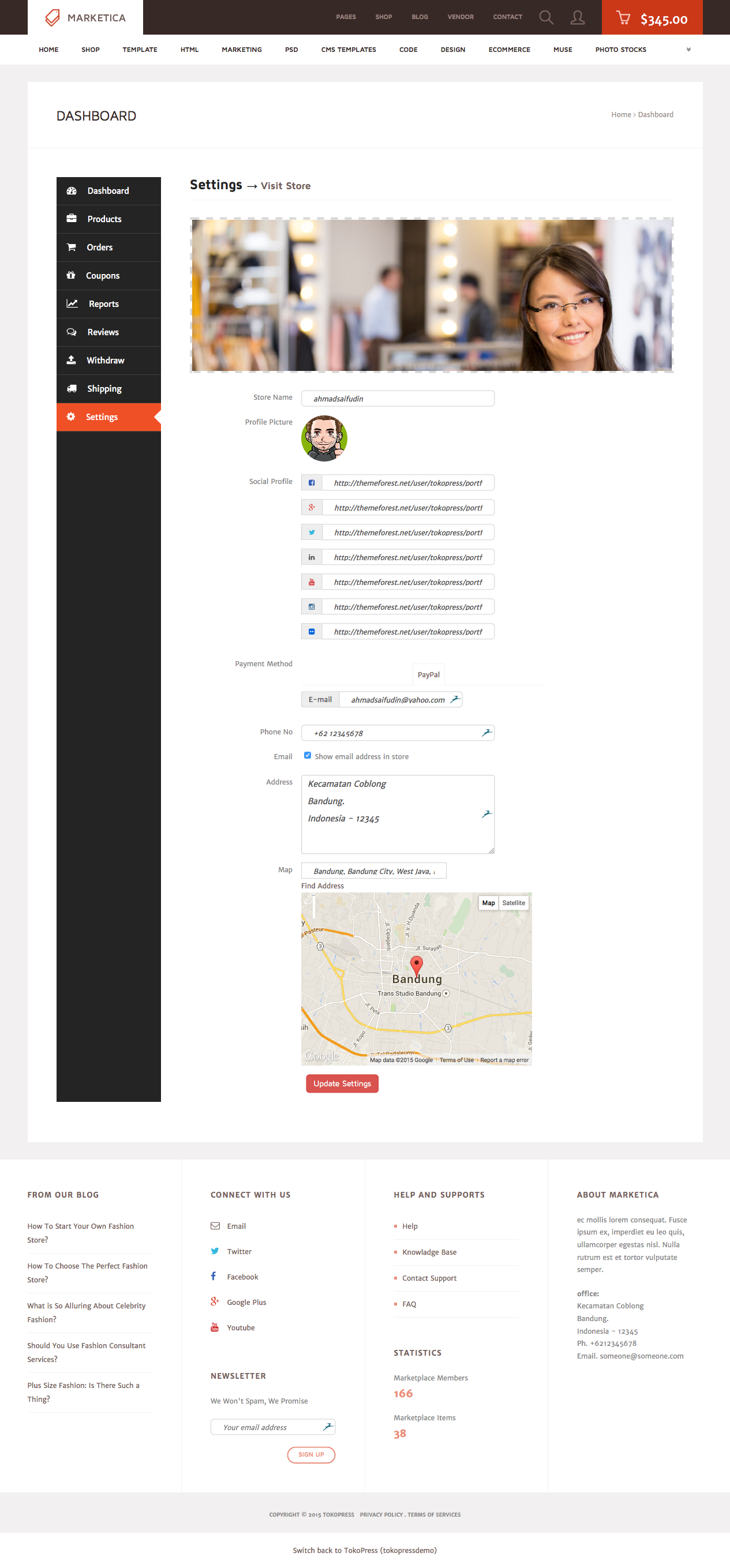
MARKETICA_PREVIEW/24_marketica2_wcvendors_shop_settings.png
MARKETICA_PREVIEW/25_marketica2_dokan_vendor_store_page.png
MARKETICA_PREVIEW/26_marketica2_dokan_vendor_review_page.png
MARKETICA_PREVIEW/27_marketica2_dokan_vendor_dashboard_page.png
MARKETICA_PREVIEW/28_marketica2_dokan_vendor_dashboard_products_page.png
MARKETICA_PREVIEW/29_marketica2_dokan_vendor_dashboard_settings_page.png
INFORMASI PLATFORM Fortun365
| NAMA SITUS | Fortun365 (situs bandar slot online & toto slot) |
|---|---|
| KATEGORI | Toto Slot, Slot Online, Live Casino |
| PLATFORM | Mobile & Desktop (Android, iOS, Windows) |
| MIN. DEPOSIT | Rp. 10.000 (Via Bank/E-Wallet/Qris) |
| RATING | 4.9/5.0 dari 2.254.808 Ulasan |
Fortun365 > Hanya Di Sini Yang Masih Bisa Bet Slot 200 Perak
Main di Fortun365 rasanya selalu nyaman. Aksesnya cepat, tampilan bersih, dan nggak pernah ada gangguan. Bener-bener enak buat hiburan malam.
Suka banget sama vibe di Fortun365. Begitu login, suasananya langsung kerasa beda — tenang tapi tetap seru. Nggak heran banyak yang betah di sini.
Menurut gue, Fortun365 itu platform yang paling stabil. Setiap buka menu selalu lancar, nggak ada lag, dan semua fitur responsif banget.
Udah cobain beberapa tempat, tapi yang paling bikin betah ya Fortun365. Desainnya rapi, navigasinya gampang, dan overall pengalaman di dalamnya solid banget.
Pertama kali coba iseng, eh malah jadi langganan. Fortun365 itu simpel, cepat, dan suasananya nyaman banget. Cocok buat hiburan santai tiap hari.
FAQ Populer: Fortun365 Situs Slot Resmi & Link Alternatif
Ringkasan pertanyaan yang paling sering muncul seputar keamanan, pasaran, pendaftaran, deposit, sampai layanan support di Fortun365.
Fortun365 menyediakan berbagai provider populer yang dikenal stabil, cepat, dan nyaman digunakan. Semua provider dipilih berdasarkan kualitas sistem dan pengalaman terbaik untuk pengguna.
Proses daftar sangat cepat, cukup isi data dasar lalu akun langsung aktif. Semua informasi pengguna dilindungi, jadi proses pendaftaran dan penyimpanan data tetap aman.
Biasanya hanya butuh beberapa menit. Sistem transaksi dibuat otomatis agar pencairan tidak memakan waktu lama.
Ya, tim support tersedia 24/7 dengan respon cepat dan ramah untuk membantu segala kebutuhan pengguna.
🎰 RTP AKURAT Fortun365

Gates of Olympus
RTP 97.12%

Starlight Princess
RTP 96.88%

Sweet Bonanza
RTP 96.51%

Mahjong Ways
RTP 97.30%

Wild Bounty Showdown
RTP 96.90%

SUPER MAHJONG DELUXE
RTP 97.05%
 PROMO
PROMO
 LOGIN
LOGIN
 DAFTAR
 LINK
LINK
 CHAT
CHAT