

 |
| Structural Design Criteria and Minimum Requirements |
Structural Design Criteria and Minimum Requirements
1. General Notes:
• Design method used is USD according to Bangladesh National Building code (BNBC) 1993, UBC 1997 and ACI 1999.
• All structural drawings shall be discovered in link with topical architectural drawings.
• Maintain BNBC / 1993 for structural requisite not allusion in the drawings or in this note sheet.
• Any details not shown in the drawing should be done according to ACI detailing manual – 1999.
• Basic wind speed = 210 km/hr
• Seismic zone – 2.
• Other loads as per BNBC 1993.
2. Foundation:
• The complex has been designed for 6-storied building (no basement)
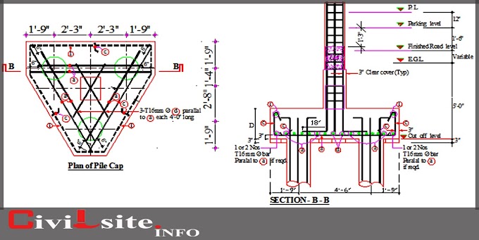
• Foundation type -footing foundation on bolli pile.
• Any loose pocket found in foundation bed is to be filled up with compacted sand of fm 1.5 min.
• Depth of foundation as per drawing.
3. Concrete:
• Type: all concrete compressive strength considered as follows:
I) f 'c = 3500 psi at 28 days cylinder strength for stone chips against.
Mixing ratio = 1:11/2:3. (for column, footing, stair, uwr, owt, lc etc.).
Ii) f 'c = 2500 psi at 28 days cylinder strength for brick chips against mixing ratio = 1:1/2:3. (for beam, slab, grade beam, lintel, drop wall, false ceiling etc.).
• Lowest cylinder strength flourished on cylinder test of
Diameter d =150mm & height 300mm
I) 28 days strength as specified in 3(a)
II) Days strength = 75% of the 28 days strength
• Curing of R.C.C work:
I) Curing time minimum 28 days
II) Method of curing:
* Horizontal surface - by pounding of water
* Other Ground - by envelop moist jute fabric and sprinkling water by huise pipe.
4. Cement:
• Ordinary Portland Cement/Type-1 Conforming 70 BOIS 232: 1974/ASTMI C150.
5. Concrete Aggregate:
A. Fine aggregates:
• 50:50 = Sylhet Sand: Local Sand for Column, Footing, UWR, OWT, Lift Core (LC), Beam, Slab, Stair etc.
• 100% Local Sand (F.M. >=1.5) for Plastering, Lintel, Drop Wall, False Ceiling etc.
B. Course Aggregates:
• Stone Chips of 3/4" down grade for Column, Footing, Stair, UWR, OWT, LC etc.
6. Water
• Potable water to be used in concrete mix.
7. Steel reinforcement
• All reinforcements are 60 grade high strength deformed bar except slab and shear reinforcement (40 grades for slab & shear).
• Yield strength of steel fy = 60,000 psi conformed to one of the following specifications: i) BDS 1313 : 1991, ii) ASTM A615m
• The following tests for reinforcing bars from random samples shall be conducted at BUET as per ODS 1313 : 1991 and test result shall be submitted to the engineer for checking and record:
i) Tensile strength test
ii) Percentage elongation test
iii) Bend/rebind test
8. Lap Length
• For tension, lap length = 30d & compression, lap length = 24d. (d = diameter of steel)
• Column laps shall be tension laps.
9. Hooks of Rebar
• For all re-bar: provide 90° standard hooks (l-bent) if not shown in the drawings.
10. Spacer Bars
• To support second layer bars in beams / slabs, use ∅25 spacer bars @ 2'-6" where required.
11. Chairs
• Use chairs of necessary dimension made of ∅10/∅12/∅16 bar to support top bars @2'-6" c/c.
12. Lap Location:
• For beam bottom bar, crease not to be give at central third axis of the span.
• For beam top bar, crease may be give at central third axis of the span.
• No more than 50% of the bars shall be attached at one place.
• Crease attached are to be fell by clamp with highest spacing or tar of d/4 or 4" where d is the effective depth of the beam.

at lap splice spacing of hoops <= d/4 but not greater than 4".
13. Development Length
• All beam and slab rears should be extended into the support up to development length.
14. Admixture
• Water proofing admixture, plasticize and jointing admixture shall be used as mentioned in the respective drawings and in the specification after approval by the engineer.
15. Water Stopper
• 12" wide PVC water stopper to be used at all construction joints bellow ground in mat, shear wall, water tank wall etc.
16. Concrete Clear Cover for Reinforcing Bars
 |
Concrete Clear Cover for Reinforcing Bars
|
17. Maximum Bars in Beams In Single Layer
• Maximum number of bars as a single layer in beam stem shall be as per aci detailing manual 1994.
18. Minimum Bar Spacing Of Column Longitudinal Bars
• Clear distance between longitudinal bars shall not be less than 1.5 times bar diameter, 1.5 times the size of course neither aggregate nor 1.5".
19. Slab End Reinforcing Details
• Free end of slab incapable of embedding of steel bar in beam / wall
• Others
 |
| Slab End Reinforcing Detail |
20. Reinforcement Details for Slab Openings

n1, n2: The number of bars which ore cut off for opening
a) The number of extra bars > n1/2
(Top and bottom bars)
b) The number of extra bars > n2/2
(Top and bottom bars)
c) The number of extra bars = 2-D12
(Top and bottom bars)
21. Recommended End Hooks
 |
| Recommended End Hooks |
22. Scope of Embedment
 |
| Scope of Embedment |
23. Additional Bar, Fastening Bar In Beam
Unless shown otherwise in the drawing(s)

24. End Hook of Stirrups
 |
| End Hook of Stirrups |
End hooks of stirrups are located alternately at top corner bar of the section.
25. Column Spice Location
 |
| Column Spice Location |
• Is area for splice of column reinforcement. Maximum 50% of total bar is spliced at one level
• H = clear column height
26. Confinement Requirements of Column At Joints For Earthquake Loading

27. Confinement Requirements Of Beam At Joints For Earthquake Loading

28. Bundle Bar

• Bars in a bundle must terminate with at least 40 bar dia stagger except where the bundle terminated.
29. Opening in R.C.C. Wall
• Not less than two no.16 bars shall be provided around all door and window openings in R.C.C. walls. The bar shall be extended beyond the corners of the openings to a distance equal to the development length but not less than 2'-0".
 |
| Opening in R.C.C. Wall |
Thanks.. for any more information write in comment box below.
You can download Structural Design Criteria and Minimum Requirements AutoCAD dwg file Click here. This file uploaded in google drive.


1 Comments
Can you share plz BNBC 2020 General Notes in my mail.
ReplyDelete